EasyTrace5000 - Browser-Based PCB CAM
EasyTrace5000 aims to be a minimalist tool that can be used by anyone to quickly turn CAD geometry into machine code. A straightforward workflow invites even beginners to start making PCBs with minimal friction, bypassing other alternatives with complex interfaces and steep learning curves.
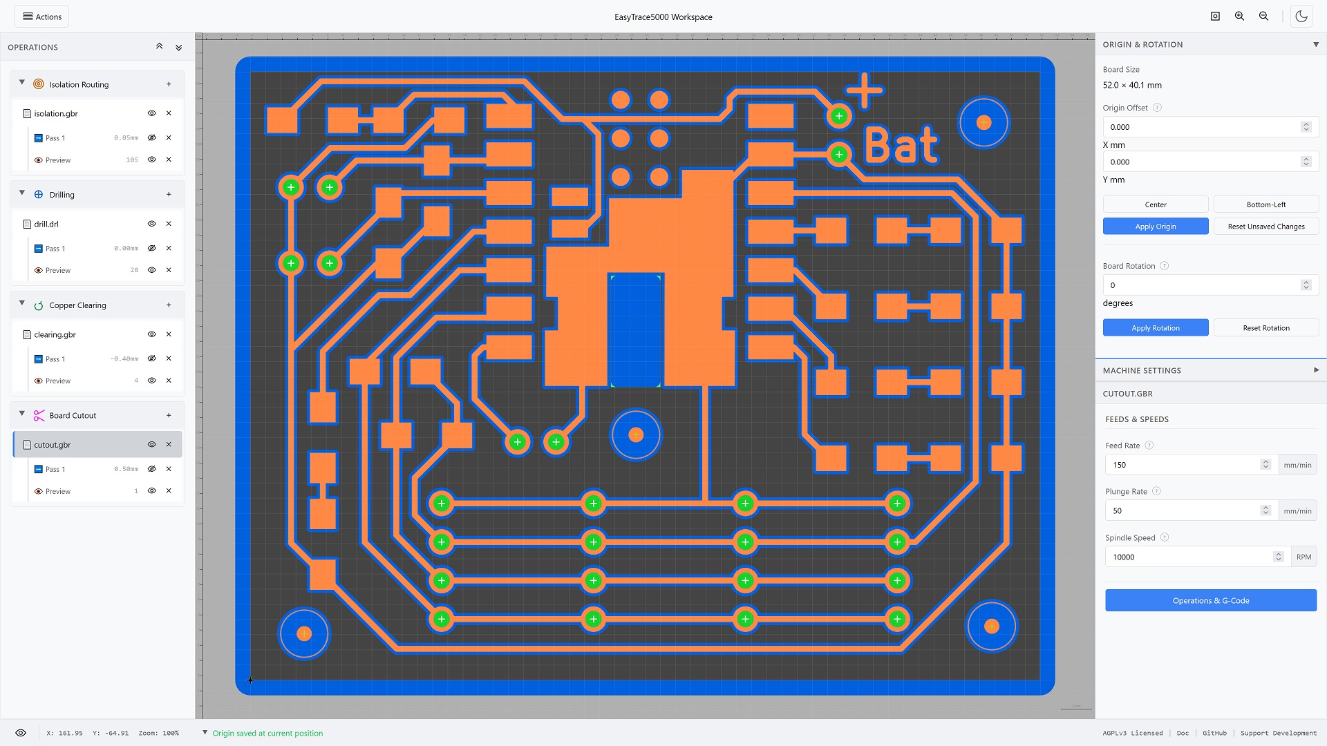
Overview of the workspace interface with a completely processed PCB example
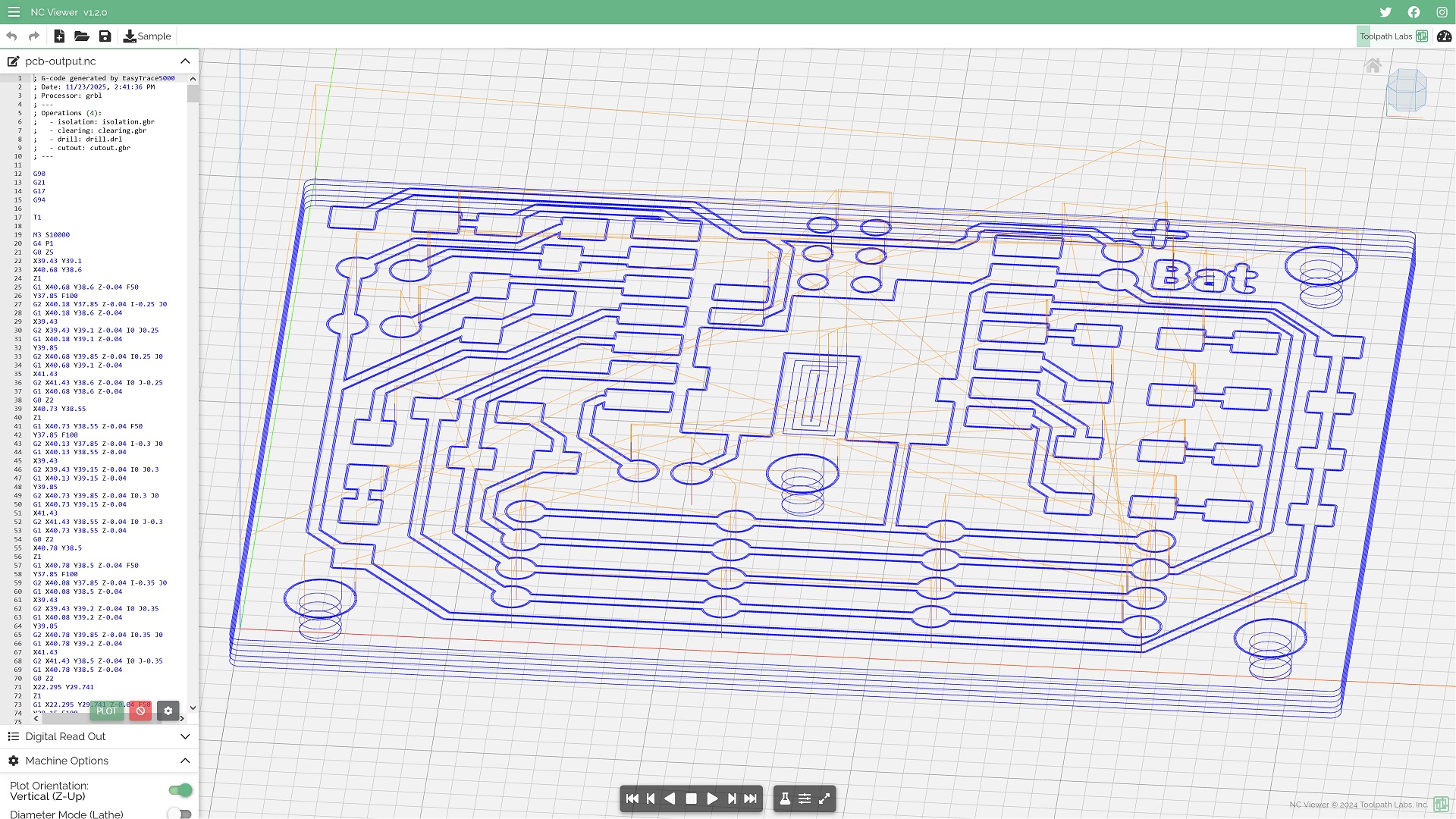
Validation of exported G-code in NCViewer, confirming the presence of reconstructed G2 arc commands

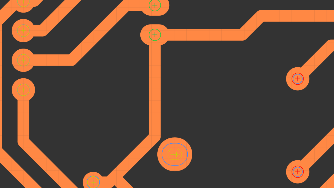
One of the advanced visualization tools can highlight all points, including all the registered ones

Another advanced tool can highlight reconstructed arcs
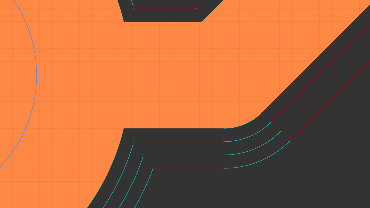
That same tool also highlights reconstructed arcs in offset geometry
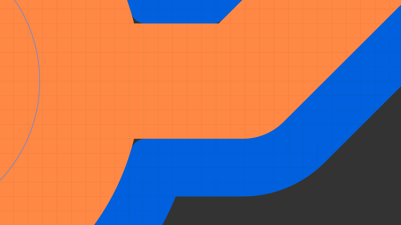
The Preview stage is a tool reach simulation and uses the reconstructed arcs
An example of multiple automated decisions about drill object size vs tool diameter

There's also an edge case of a hole almost the size of a tool that won't try to mill a helix entry
Approach
EasyTrace5000 started as a side-project to build an isolation routing pipeline for internal use but quickly turned into an iterative experiment in what was possible to do in a browser. The parsing and rendering subsystems were structured first and helping then to define the data structures used by the geometry modules. With boolean operations, arc-reconstruction, and analytic offsetting operational, the focus shifted to toolpath planning and G-code exporting. The user interface was developed incrementally to expose functionality while always focusing on a predictable user-experience. Once the subsystems acted as a single workflow, the entire backend underwent a major optimization refactor.
Challenges
To ensure cross-platform compatibility, the app was designed to run in the browser. Being client-side cuts infrastructure costs and guarantees user privacy but limits available resources. Despite these constraints, preserving lossless geometry throughout was a priority. The result is a processor that, unlike most alternatives, can recover and output virtually lossless G2/G3 arcs. This required fine-tuning each subsystem:
Workflow UX
The original plan involved a linear three-stage workflow: X/Y geometry parameters, Z-axis movements and finally feeds, speeds plus machine settings. As the modules evolved, project-wide machine parameters were decoupled into their own dedicated section. G-code exporting eventually required a final stage to handle the last set of output settings and toggles. To support this logic, the Navigation Tree nests operation stages under the source file. Unlike FlatCAM’s stage list approach, this enforces a parent-child hierarchy that keeps processed state objects bound to their original file.
Visualization System
As tool functionality grew, so did rendering complexity. It was fundamental to display all information clearly without overwhelming the user. Operational geometry is color-coded, including dynamic logic to show the relationship between tool diameter and Drill Op. feature sizes. As the offsetting engine started generating multiple passes correctly, the resulting thousands of path objects turned individual draw call overhead into a significant bottleneck. Because caching is ineffective with zooming and panning, the renderer was optimized with draw call batching, level-of-detail scaling, and viewport culling to skip small or off-screen objects. Complementary advanced visualization tools were also created to help debug the development of other systems.
File Parsing
Gerber, Excellon and SVG encoding is well documented but there are EDA export variations. An intermediary plotting module was created to control how data flows into the tool. Before being translated into unified data-structures, raw geometry is interpreted to detect edge cases. This normalizes artifacts such as mistagged circular obround shapes, obround "rectangles" with rounded corners, implicit polygons with out-of-order segments and complex repetitive macros. Geometry that isn't supported by the offsetting algorithms is also interpolated preemptively.
Geometry Engine
The core requirements were boolean unions for overlapping object fusion and precise offsetting for lossless toolpath geometry. Clipper2 WASM was selected for the boolean operations, paired with a custom arc reconstruction algorithm to mitigate the library's inherent polygonization constraints. With no compatible off-the-shelf solution capable of processing these raw curves as required, a lightweight analytic system was implemented. To manage floating-point inaccuracies inherent to sub-millimeter calculations multiple safeguards were necessary to prevent distortion of arc objects. The final engine integrates other essential accessory functions, including path/polygon pre-processing for Clipper2 and stitching logic for implicit regions with out-of-order segments.
Path Planning
Transitioning to machine code required an intermediary data-structure to hold spatial movement representations of the offset geometry. Machining logic is then inserted around these objects and everything is optimized to minimize job time. The algorithm sorts objects via nearest-neighbor search and groups "staydown" clusters to eliminate redundant Z-axis movements. It also rotates closed-loop entry points to align with the tool's approach and filters collinear segments without invalidating fragile arc definitions. This produces a clean, machine-agnostic motion plan that is easily serialized into any controller dialect, from GRBL to Roland RML.
Extensibility
The tool was designed with a modular architecture to ensure long-term maintainability and streamline the independent evolution of its subsystems. This separation of concerns allows for the seamless replacement or addition of new functions. To limit the accumulation of technical debt as development continues, anticipating future requirements helps avoid resource intensive refactors. For example, the foundations of a unit management system are already partially implemented and the future UV/Fiber Laser pipeline can be readily integrated by repurposing resources already in use.
Results
- Complete client-side application requiring no server infrastructure
- Native parsers for Gerber RS-274X, Excellon, and SVG with analytical curve preservation
- Custom algorithm reconstructs G2/G3 arcs from polygonized Clipper2 geometry
- Four operation types: isolation routing, drilling, copper clearing, board cutout
- Intelligent drill strategy with automatic peck cycle, helical milling, or centerline slot based on tool-to-feature ratio
- Analytic offset engine with arc-preserving rounded joints for internal and external passes
- Three-stage toolpath pipeline with staydown clustering and nearest-neighbor optimization
- Tab/bridge generation for cutout operations with arc-aware path splitting
- Canvas renderer capped at 60fps with batching and LOD/viewport culling
- Six post-processor targets: GRBL (stable), GrblHAL, Marlin, LinuxCNC, Mach3, Roland RML (experimental)